Throttle Screw M5 520001184
Product Name: Throttle Screw M5 520001184
Description:
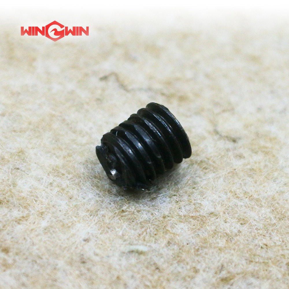
This component is a throttle screw, specifically an M5 threaded metering screw, designed as a flow control component for the abrasive delivery system (sand valve / abrasive regulator) on waterjet cutting equipment . It is a precision-machined consumable part that regulates the volume of abrasive garnet entering the cutting head mixing chamber.
In the abrasive regulator assembly, the throttle screw acts as a variable orifice. When rotated, it adjusts the distance between the screw tip and the valve seat, controlling the cross-sectional area through which abrasive particles flow. The M5 designation indicates a metric thread diameter of 5mm. The specific part number 520001184 corresponds to a particular length and tip geometry for a specific waterjet system.
Applications:
Regulates abrasive flow rate in the sand valve assembly of abrasive waterjet cutting systems
Controls garnet delivery into the mixing chamber for optimal cutting efficiency
Serves as a fine-tuning mechanism for abrasive metering during material processing
Suitable for ultra-high pressure waterjet systems operating at 60,000–90,000 PSI
Features:
M5 Metric Thread: Standard 5mm diameter metric threading for compatibility with industry-standard abrasive regulators
Precision Machined: Manufactured to exact tolerances for consistent flow regulation and smooth adjustment
Wear-Resistant Material: Constructed from hardened steel or stainless steel to withstand abrasive particle flow
Lock Nut Integration: Designed to work with a locking nut to maintain set position during machine operation
Adjustable Flow Control: Allows operator to increase or decrease abrasive volume by rotating clockwise or counter-clockwise
Maintenance:
Performance Monitoring: Abrasive flow that is too low reduces cutting efficiency; flow that is too high causes clogging. Adjust the throttle screw accordingly .
Replacement Indicators: Replace the throttle screw immediately if the tip shows visible wear, erosion, or deformation. A worn throttle screw will cause inconsistent abrasive flow .
Proper Gap Setting: After replacement, maintain a gap of approximately 0.05 mm between the throttle screw and the valve core. Push the valve core firmly and observe whether it moves freely; repeat adjustment if necessary .
Installation Procedure:
Use a screwdriver to rotate counter-clockwise, adjusting the throttle screw to the appropriate position
Insert the locking screw from the other side of the connector
Slide the lock nut onto the connector, then install the combination washer
Screw the connector assembly into the sand valve body and tighten with a wrench
Flow Direction: Rotating the throttle screw clockwise (into the valve) decreases abrasive flow; rotating counter-clockwise (outward) increases abrasive flow. The negative pressure gauge reading will change accordingly .
System Verification: Before adjusting the throttle screw, confirm that all combination washers are intact, the supply plastic tube is undamaged and fully inserted into the mixing chamber, system operating pressure is normal, and the jewel nozzle is not damaged or causing stream divergence .
Lock Nut Security: After achieving uniform and continuous abrasive flow, re-tighten the lock nut to secure the throttle screw position .
Full Depressurization: Always fully depressurize the waterjet system and follow lockout/tagout procedures before replacing or adjusting the throttle screw .