Electronic-Shift-Assembly-Manifold-20499180
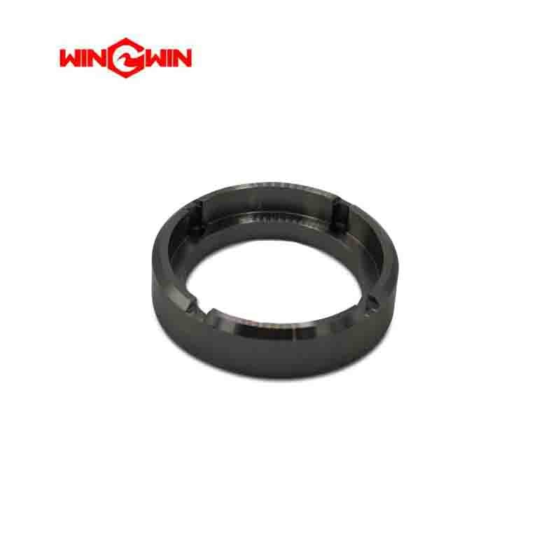
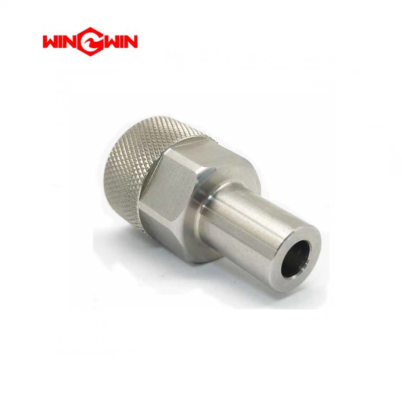
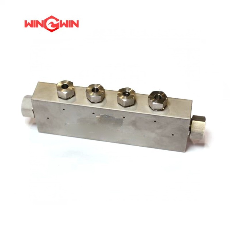
Product Name: Electronic Shift Assembly Manifold / Pilot Valve Block (Part No. 20499180)
Description:
This component is an electronic shift assembly manifold, also known as a pilot valve block or hydraulic manifold block. It serves as the central fluid distribution hub for the electronic shifting mechanism in a waterjet intensifier pump . The manifold contains precision-machined internal flow passages that direct pilot hydraulic oil to actuate the main directional control valve, which controls the reciprocating motion of the intensifier piston .
The electronic shift assembly manifold integrates multiple hydraulic control functions into a single, compact block. It typically includes mounting interfaces for:
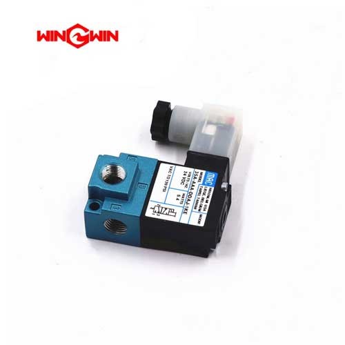
Electronic pilot solenoid valves (directional control valves)
Check valves (electronic shift assembly check valve, Part No. 80085756)
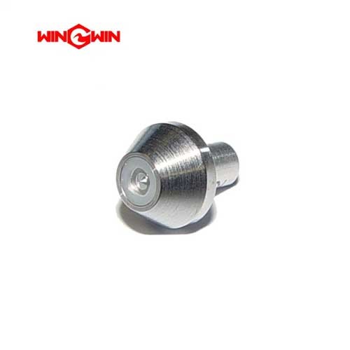
Firing pin mechanism (electronic shift assembly firing pin, Part No. 20457897)
Pressure sensors or switches
Hydraulic line ports for supply and return connections
This manifold is rated for continuous operation at 60,000-90,000 PSI (approximately 4,137-6,200 bar) and is manufactured from high-strength, corrosion-resistant steel to withstand extreme pressure cycling. It is an OEM direct replacement part compatible with KMT AccuStream, H2O Jet, Flow, and other standard waterjet intensifier systems .
Applications:
Serves as the central hydraulic control hub for the electronic shift assembly in waterjet intensifier pumps
Directs pilot oil flow to actuate the main directional control valve for intensifier piston reversing
Provides mounting interfaces for solenoid valves, check valves, firing pins, and pressure sensors
Used when the intensifier fails to shift direction, shifts erratically, or during major pump overhauls
Compatible with 60,000-90,000 PSI waterjet intensifier systems
Features:
Precision-Machined Internal Passages: Cross-drilled flow ports direct pilot oil with minimal turbulence and pressure loss
Corrosion-Resistant Construction: High-strength steel with protective coating for durability in waterjet environments
Integrated Functional Design: Combines multiple hydraulic control functions into a single block, reducing external leak paths
High-Pressure Rating: Engineered for continuous operation at 60,000-90,000 PSI (4,137-6,200 bar)
Direct OEM Replacement: Fully compatible with major waterjet intensifier systems
Semi-Wear Component: Under normal operating conditions, the manifold itself is not a high-wear consumable but requires periodic inspection for internal erosion or damage
Maintenance:
When to Replace (Failure Diagnosis) :
Persistent External Hydraulic Leakage: Oil weeping from the manifold body or at component interfaces indicates seal failure or manifold damage
Intensifier Fails to Shift Direction: If the pump stops at the end of stroke and does not reverse, the shift assembly manifold may have internal damage or blockage
Erratic or Inconsistent Shifting: Irregular cycling, "double stroking," or slow shifting indicates shifting issues that may originate in the pilot manifold block
Overheating Components: If the manifold body becomes hotter than normal, internal leakage or bypass may be occurring
Contamination-Related Issues: Dirt or debris in the pilot oil can cause internal passages to clog or valve components to stick
Visible Internal Erosion: During overhaul, inspect the manifold internal passages for pitting, scoring, or erosion
Inspection and Replacement Guidelines :
Full Depressurization (Critical) : Before any maintenance, place the main electrical disconnect in the OFF position, bleed down all high-pressure lines, fully depressurize the hydraulic system, and follow lockout/tagout procedures
Clean Area Maintenance: Perform manifold service in a designated clean area to prevent contamination of internal passages with debris or abrasive particles
Component Inspection Sequence :
Remove the electronic shift assembly manifold from the hydraulic system
Disassemble and remove all mounted components (solenoid valves, check valves, firing pin assembly)
Clean the manifold block thoroughly with diesel or appropriate cleaning solvent
Inspect internal passages for blockages, scoring, pitting, or erosion
Check all sealing surfaces and threaded ports for damage
Seal Replacement: Always replace all O-rings, backup rings, and gaskets when servicing the manifold
Torque Compliance: When reinstalling, tighten all mounting bolts and component fittings to the specific torque values listed in the equipment service manual
Thread Lubrication: Apply high-pressure anti-seize lubricant to threads during reassembly to prevent galling
Replacement Criteria: Replace the manifold immediately if cracks are visible, internal passages are severely eroded or clogged beyond cleaning, or threads are damaged. Do not attempt to repair a cracked or severely eroded manifold block
Cross-Reference Part Numbers: This manifold works in conjunction with Electronic Shift Assembly Check Valve (80085756) and Electronic Shift Assembly Firing Pin (20457897). When servicing the shift assembly, all components should be inspected and replaced as needed
Integration with Electronic Shift Assembly Components:
The electronic shift assembly manifold (20499180) works together with:
Electronic Shift Assembly Check Valve (80085756) : Controls pilot oil flow direction
Electronic Shift Assembly Firing Pin (20457897) : Transmits mechanical force from solenoid to hydraulic valve
Electronic Pilot Solenoids: Electrical actuators that shift the pilot spool