20457447-Manifold-hydraulic-side-mount
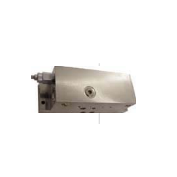
Product Name: Side-Mount Hydraulic Manifold (Part No. 20457447)
Description:
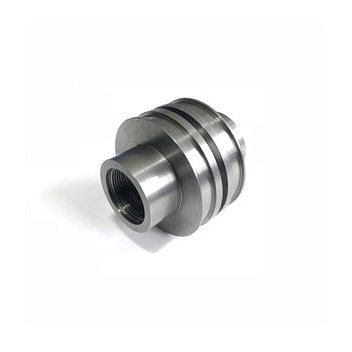
The Side-Mount Hydraulic Manifold (20457447) is a specialized fluid distribution block designed for the low-pressure hydraulic circuit of a waterjet intensifier pump . Its primary function is to route and direct pressurized hydraulic oil from the pump's directional control valve to the correct side of the hydraulic cylinder, enabling the reciprocating motion that drives the high-pressure plunger .
Unlike a "top-mount" configuration, this "side-mount" manifold attaches to the side of the intensifier's end bell assembly, allowing for a more compact machine layout. Machined from high-strength steel, it incorporates precision-machined flow paths and porting for components like the shift valve, pressure switches, and supply lines .
Applications:
Controlling the flow of hydraulic oil to the intensifier cylinder to create the forward and return stroke.
Housing and supporting the directional shift valve assembly.
Serving as the central connection point for hydraulic hoses from the power unit.
Compatible with 60K waterjet intensifier systems.
Features:
Side-Mount Configuration: Attaches to the side of the intensifier end bells.
Integrated Circuitry: Internal passages direct fluid for precise piston control.
Durable Material: Constructed from high-strength alloy to withstand pressure up to 60,000 PSI .
Precision Porting: CNC-machined ports for leak-free sealing of threaded fittings.
Maintenance:
Leak Inspection: Regularly check for hydraulic oil seepage at the manifold base and fittings. Oil leaking from the manifold / end bell interface indicates seal failure .
Valve Service: The shift valve mounted on the manifold requires periodic cleaning or replacement if the intensifier fails to change direction .
Semi-Wear Part: While durable, internal port erosion or thread damage can occur over time due to vibration and maintenance cycles .
Torque Compliance: When reinstalling, tighten all cap screws to 25 ft-lbs [34 Nm] in a figure-eight pattern to ensure an even seal .
Lockout/Tagout: Always fully depressurize the hydraulic system and follow lockout/tagout procedures before servicing .