CP022017-172-Connection-Flangefor-BFT-waterjet
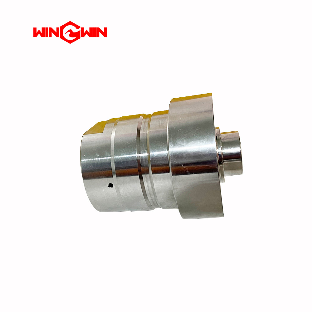
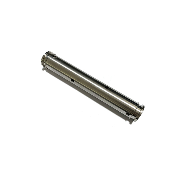
Product Name: Connection Flange / CP022017/172
Description:
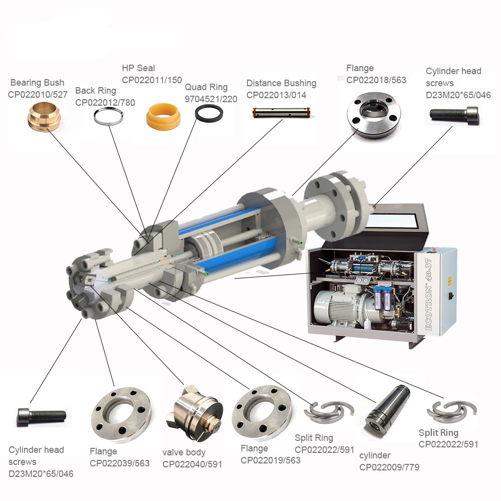
The CP022017/172 Connection Flange is a high-strength stainless steel flange specifically designed for BFT waterjet intensifier pumps . It is an essential component of the intensifier assembly, serving as the low-pressure connection flange located between the hydraulic cylinder and the high-pressure cylinder . Additionally, it acts as the water connection flange on the water intake side of the pump .
Manufactured from a hardened, corrosion-resistant material, this flange is engineered to withstand the immense pressure cycling of the hydraulic system, ensuring a rigid and leak-proof mechanical interface between the major pump components.
Applications:
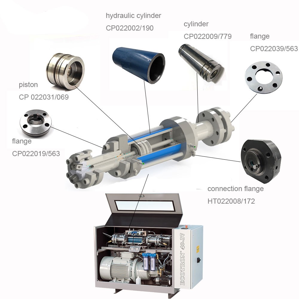
Serves as a connection interface between the hydraulic cylinder and the high-pressure cylinder in BFT intensifier pumps .
Acts as a water intake flange (low-pressure side) for the intensifier pump.
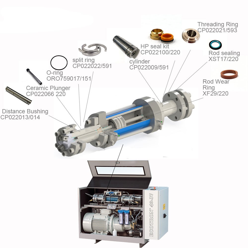
Used as a standard component in CP022001/2 and HT022012/172 intensifier assemblies .
Compatible with BFT, BHDT, WJS, Maximator Jet, and STM waterjet systems.
Features:
Hardened Stainless Steel Construction: Provides excellent corrosion resistance and structural integrity under extreme pressure cycling.
Precision-Machined: Manufactured to exact OEM tolerances for a perfect fit between the hydraulic and high-pressure cylinders.
Critical Structural Component: This flange is bolted into the pump stack and is responsible for maintaining the alignment of the intensifier components.
Direct OEM Replacement: Cross-referenced as part numbers MJ0040002 and 1-15603 .
Maintenance:
Inspection: During major pump overhauls, inspect the flange for cracking, thread damage, or corrosion on the mating surfaces.
Surface Condition: The precision-ground mating faces must be free of nicks or debris to ensure a leak-free seal against the cylinder.
Full Depressurization (Critical): Before any maintenance, lock out the main electrical disconnect, fully depressurize the high-pressure water system and the hydraulic system, and follow lockout/tagout procedures.
Torque Compliance: When reinstalling the cylinder head screws that secure this flange, tighten them to the specific torque values listed in the equipment service manual using a crisscross pattern to ensure even clamping.