Actuator-Assembly-Shift-Sensor-20457264
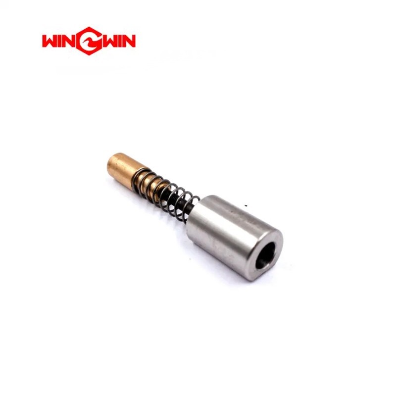
Product Name: Actuator Assembly / Shift Sensor Assembly (Part No. 20457264)
Description:
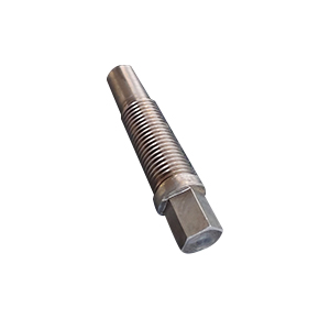
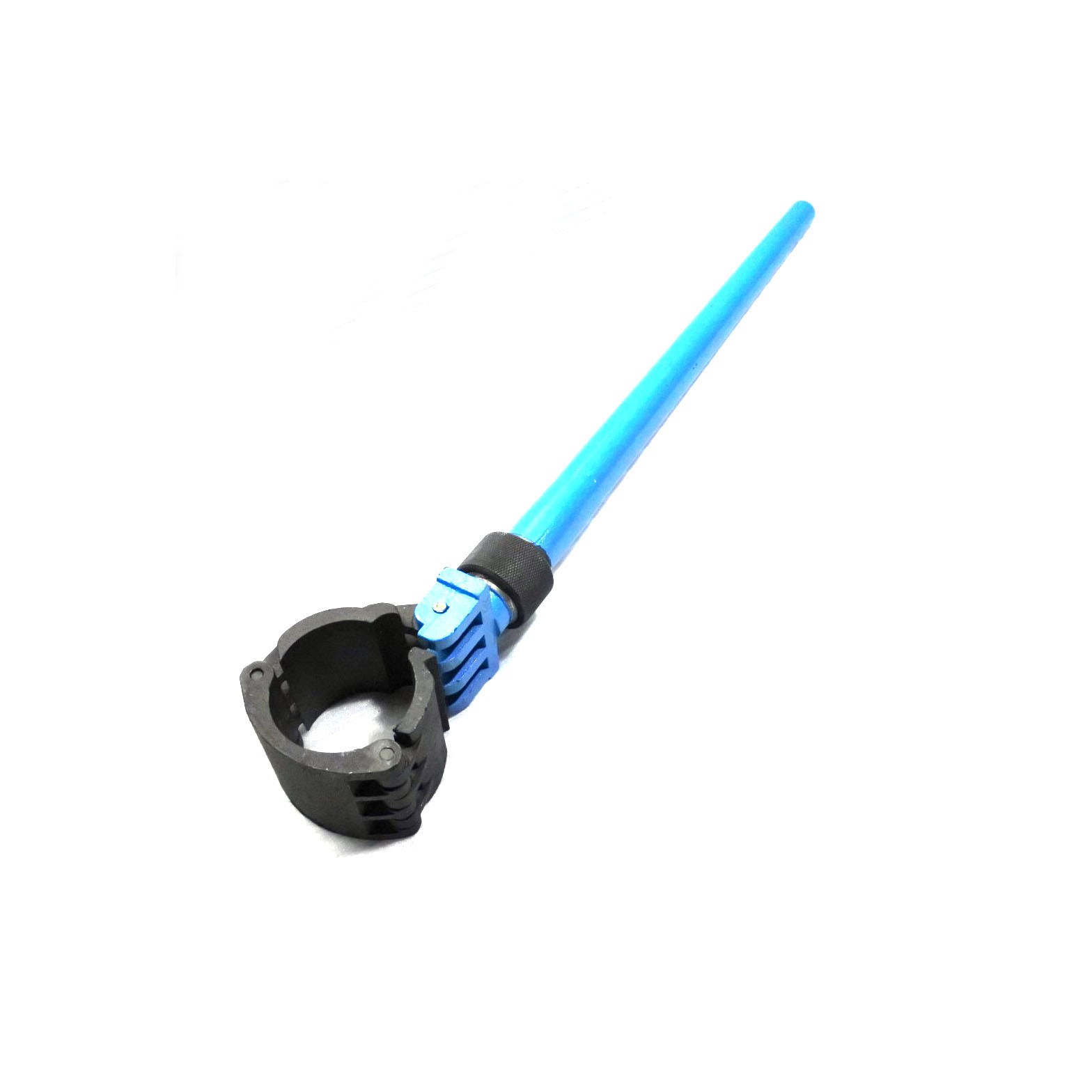
This component is an actuator assembly, specifically a shift sensor assembly (often referred to as a Hall Effect sensor or proximity switch assembly) for the intensifier pump of a waterjet cutting system. Its primary function is to detect the end-of-stroke position of the hydraulic piston as it reciprocates within the cylinder . By sensing the piston's position, the shift sensor sends a precise electrical signal to the pump's control system, triggering the pilot valve to reverse the hydraulic flow. This continuous, automatic back-and-forth switching is what drives the intensifier to generate ultra-high pressure water .
This part is a critical component in the pump's electronic control loop. It consists of a durable sensing element (the "proximity switch" or "Hall sensor") and a target magnet or pin (the "actuator") that travels with the piston . Proper function of this assembly is essential for consistent intensifier cycling, stable pressure output, and avoiding erratic operation . It is a common replacement part for standard waterjet intensifier systems and is known to be compatible with various brands including H2O Jet, KMT, and others .
Applications:
Detects the hydraulic piston's end-of-stroke position to signal the intensifier to reverse direction.
Generates the timing signal for the pump's directional control valve (solenoid / pilot valve) .
Used when the intensifier fails to shift, shifts erratically, or shifts with a loud "bang" .
Suitable for 60,000-90,000 PSI ultra-high pressure waterjet intensifiers.
Features:
Non-Contact Sensing: Uses Hall Effect (magnetic) technology for reliable, wear-free operation if properly adjusted .
Robust Construction: Designed to withstand the high vibration and moist environment of the waterjet pump.
Critical Timing Component: Provides the essential feedback for stable and efficient pump cycling .
Adjustable Mounting: Typically features slotted mounting holes or a threaded body to adjust the sensor gap .
Maintenance:
When to Replace (Failure Diagnosis):
Pump Fails to Shift: The intensifier stops at the end of its stroke and does not reverse direction .
Erratic Operation: The pump cycles irregularly, showing inconsistent shift timing or "double cycling."
Missing Indicator Light: If the system uses a visual indicator, the light on the sensor does not change state when the piston passes.
Sensing Failure: Using a metal test piece (e.g., a screwdriver), the sensor does not activate when the target is passed in front of it .
Physical Damage: The sensor cable is cut, the housing is cracked, or the target magnet is lost/demagnetized.
Testing and Replacement Guidelines (General Procedure):
Full Depressurization (Critical): Before any maintenance, always fully depressurize the waterjet system (hydraulic and high-pressure circuits), disconnect electrical power, and follow lockout/tagout procedures .
Visual/Electrical Test:
Remove the sensor from its mounting bracket.
Reconnect the electrical plug (if disconnected).
Turn on the control power (do not start the high-pressure pump).
Pass a steel tool or magnet near the sensing face. The LED indicator (if equipped) should turn on/off . If it fails to respond, replace the sensor.
Adjustment (Check Before Replacement): Ensure the air gap between the sensor tip and the target actuator is set correctly (usually 1-3mm). If the gap is too large, the sensor may not trigger; if too small, it may be damaged .
Interchanging: If troubleshooting a "no shift" condition, the left and right sensors can sometimes be swapped to test if the fault is in the sensor itself or the control circuit .
Clean Installation: When replacing, ensure the mounting surface is clean and the sensor is secured without over-tightening the lock nut.
Cross-Reference Information: This part number is directly referenced as a shift sensor (position switch) assembly. Alternative part numbers may include 301011-3-A, B-8346-1, and 011275-1 .