Waterjet-pump-CP022018-563
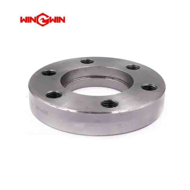
Product Name: High-Pressure Flange / Intensifier Connection Flange (Part No. CP022018/563)
Description:
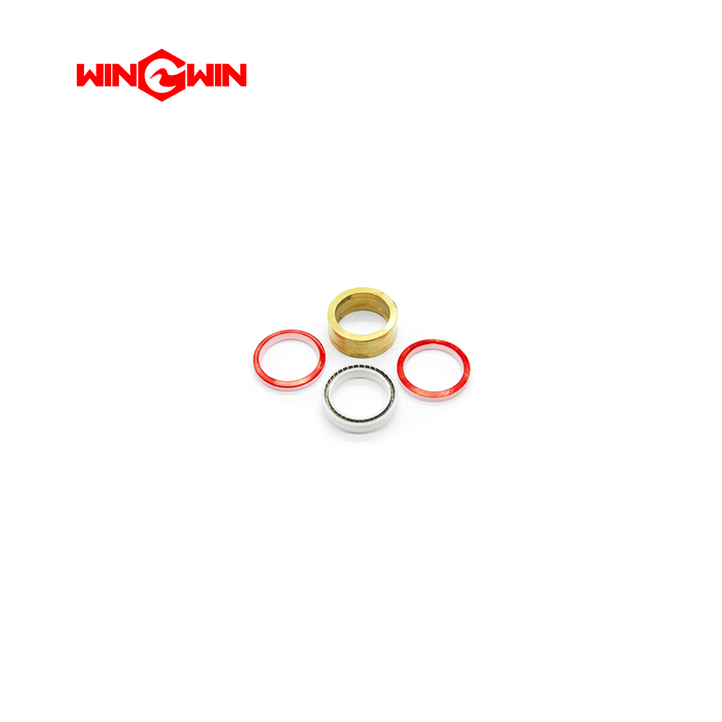
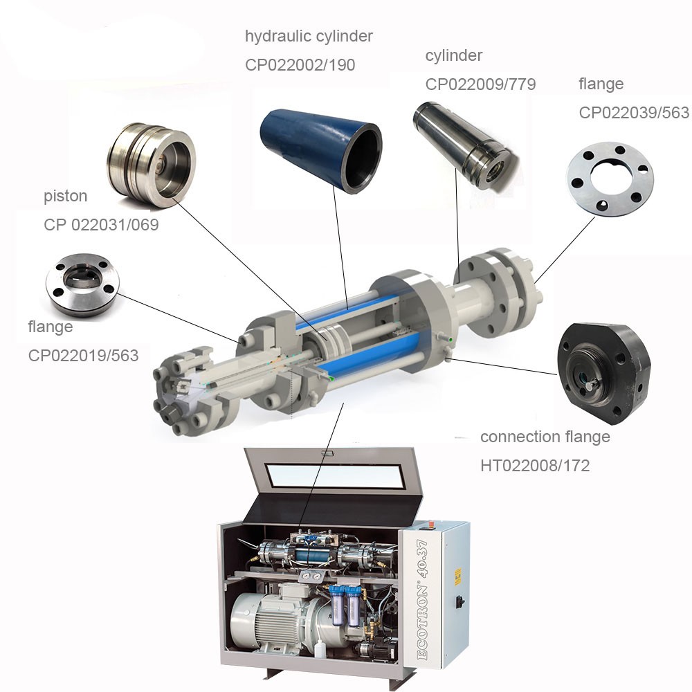
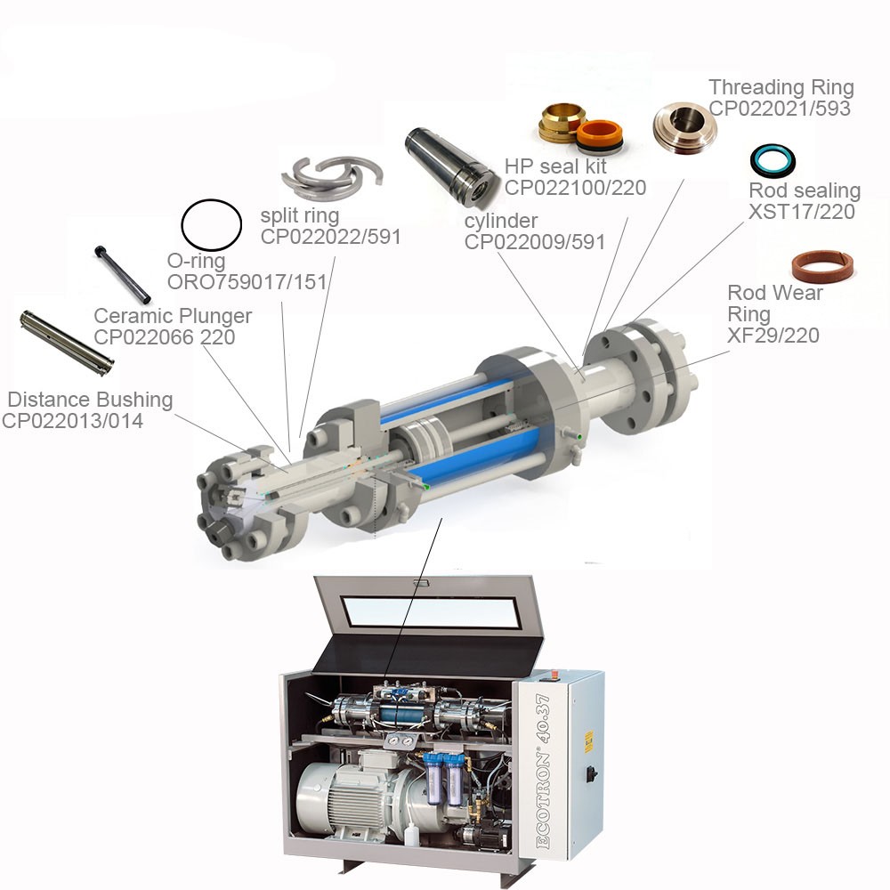
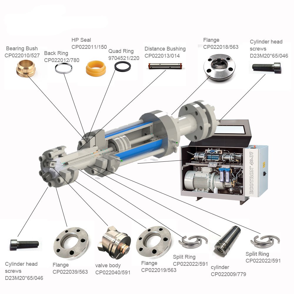
This component is a precision high-pressure flange specifically designed for BFT waterjet intensifier pump assemblies . It serves as a critical structural connector, acting as a connecting flange or reinforcement flange within the intensifier stack, linking major hydraulic components such as the hydraulic cylinder, high-pressure cylinder, and end bells . The flange provides a rigid, leak-proof interface capable of withstanding the extreme clamping forces and pressure cycling (up to 60,000–94,000 PSI / approx. 4,137–6,480 bar) inherent in waterjet operation.
This component is listed as Item 35 in the CP022001/2 intensifier parts diagram and as Item 35 in the HT022012/172 parts diagram . Typically manufactured from high-strength, corrosion-resistant stainless steel or hardened alloy, the flange maintains critical alignment and structural integrity of the entire intensifier assembly, preventing misalignment that could lead to premature seal wear or oil manifold damage.
Applications:
Connects and aligns critical components within the BFT waterjet intensifier stack (hydraulic cylinder, high-pressure cylinder, and end bells)
Serves as a reinforcement flange to distribute clamping forces evenly across the intensifier assembly
Maintains structural rigidity and alignment under extreme pressure cycling
Used during major pump overhauls, complete intensifier rebuilds, or when component alignment is compromised
Compatible with BFT intensifier assemblies CP022001/2 and HT022012/172
Features:
High-Strength Stainless Steel / Alloy Construction: Provides excellent corrosion resistance and structural integrity under extreme pressure cycling up to 60,000–94,000 PSI (4,137–6,480 bar)
Precision-Machined Mating Surfaces: Features accurately machined sealing surfaces and bolt hole patterns for proper fit and alignment within the intensifier stack
Critical Structural Component: Essential for maintaining the coaxial alignment of the intensifier stack, which is vital for preventing seal failure, pressure loss, and oil manifold damage
Direct OEM Replacement: Listed as Item 35 in BFT intensifier CP022001/2 parts list and Item 35 in HT022012/172 parts list
Maintenance:
Failure Diagnosis (When to Inspect/Replace):
External Fluid Leakage: Visible water or hydraulic oil weeping from the flange-to-cylinder interface indicates seal failure or loss of clamping force
Alignment Issues: Difficulty reassembling the intensifier or signs of stress on the oil manifold may indicate a warped or damaged flange
Cracked or Deformed Flange: Any visible cracking, distortion, or severe corrosion of the flange body warrants immediate replacement
Thread Damage: Stripped, galled, or corroded mounting bolt holes prevent proper clamping and require replacement
Intensifier Leakage: External oil or water leaks from between sections of the pump stack may indicate a compromised flange interface
Scheduled Overhaul: It is standard practice to inspect flanges during major pump overhauls (typically every 4,500–5,000 operating hours) and replace them if any wear or damage is detected
Inspection and Replacement Guidelines:
Full Depressurization (Critical): Before any maintenance, place the main electrical disconnect in the OFF position, fully depressurize both the high-pressure water system and the hydraulic system, and follow lockout/tagout procedures
Use Alignment Fixture: An intensifier assembly fixture must be used to square the end bells with each other during reassembly. If components are assembled out of alignment, oil manifold leakage and breakage may occur
Torque Compliance (Critical): When reinstalling, tighten the mounting bolts in a crossing (staggered) pattern to the specific torque values listed in the equipment service manual (e.g., 160 Nm / 120 ft-lbs for tie rod nuts). Uneven torque can cause warpage and leaks
Clean Installation: Thoroughly clean all mating surfaces and bolt holes with a soft cloth and compatible solvent. Remove all debris, old seal residue, and corrosion
Lubrication: Apply high-pressure anti-seize lubricant to bolt threads during reassembly to prevent galling and ensure accurate torque application
Inspect Mating Surfaces: Check the flange sealing surfaces for nicks, scratches, pitting, or erosion. Any damage will compromise the seal integrity
Replace if Damaged: Replace the flange immediately if cracks, severe corrosion, thread damage, or sealing surface damage is detected. Do not attempt to repair a cracked or severely damaged flange
Cross-Reference Information: This flange is listed as Item 35 in CP022001/2 parts diagram and Item 35 in HT022012/172 parts diagram ; it works in conjunction with the cylinder (CP022002/190) and other intensifier components
Storage: Store spare flanges in a clean, dry environment to prevent corrosion and surface damage before use
Cross-Reference Information:
BFT #: CP022018/563
Also known as: High-Pressure Flange, Connection Flange, Intensifier Flange, Reinforcement Flange
Works with: Cylinder (CP022002/190), End Bells, Hydraulic Cylinder, High-Pressure Cylinder
Rated Pressure: 60,000-94,000 PSI (4,137-6,480 bar)