Shift-Sensor-Housing-and-Cable-Assembly-20458290
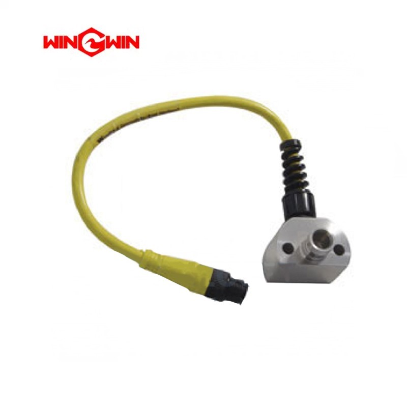
Product Name: Shift Sensor Housing and Cable Assembly (Part No. 20458290)
Description:
The Shift Sensor Housing and Cable Assembly is a critical electronic feedback component in the hydraulic control loop of a waterjet intensifier pump. It houses the magnetic proximity switch (sensor) that detects the position of the intensifier piston and transmits this signal via an integrated cable to the machine’s controller .
As the piston approaches the end of its stroke, the sensor detects the magnetic field from a target magnet on the piston assembly. This signal is sent through the cable to the pilot valve, triggering the hydraulic system to reverse direction and sustain continuous ultra-high pressure water generation. A failure in this assembly will cause the intensifier to stop cycling, leading to a loss of cutting pressure.
Applications:
Detects the end-of-stroke position of the hydraulic piston in waterjet intensifier pumps .
Sends the electrical signal to the controller or directly to the pilot valve to reverse the hydraulic flow.
Essential for maintaining continuous, stable cutting pressure in 60,000-94,000 PSI systems.
Features:
Integrated Design: Combines the sensor (proximity switch) and the shielded cable into a single sealed assembly, simplifying replacement and improving reliability.
Non-Contact Sensing: Utilizes magnetic (Hall Effect) technology for wear-free operation, ensuring long service life.
Critical Timing Component: Directly responsible for the precise shift timing that keeps the intensifier cycling efficiently .
Direct OEM Replacement: Interchangeable with standard waterjet intensifier components.
Maintenance:
Failure Diagnosis (When to Replace):
Intensifier Fails to Shift: If the pump runs but the piston stops at the end of its stroke and does not reverse, the sensor or its cable is likely faulty.
No Signal / Error Code: The machine controller displays a "No Shift Signal" or similar sensor fault.
Physical Damage: The cable is cut, crushed, or the sensor housing is cracked.
Intermittent Operation: The pump shifts erratically, sometimes working and sometimes stopping, indicating a broken wire inside the cable insulation.
Testing and Replacement Guidelines:
Full Depressurization (Critical): Lock out the main electrical disconnect. Fully depressurize the high-pressure water system and the hydraulic system. Severe injury can result if the machine is not properly locked out.
Visual Inspection: Before replacement, inspect the cable for any signs of crushing, cuts, or abrasion.
Sensor Testing: Remove the sensor and pass a steel tool (e.g., screwdriver) in front of the sensing face while connected to power (low voltage only). An LED indicator should toggle on/off. If no LED is present, test for voltage change with a multimeter.
Air Gap: When installing the new assembly, ensure the distance (air gap) between the sensor tip and the target magnet is set correctly (typically 1-3 mm) as per the equipment manual.
Cable Routing: Route the new cable away from moving parts, hydraulic hoses, and sharp edges. Secure it with cable ties to prevent vibration damage.
Torque Compliance: Tighten the sensor mounting nut to the specified torque to prevent loosening due to pump vibration.