High-Pressure-Seal-20458113
Product Name: High Pressure Seal Assembly (Part No. 20458113)
Description:
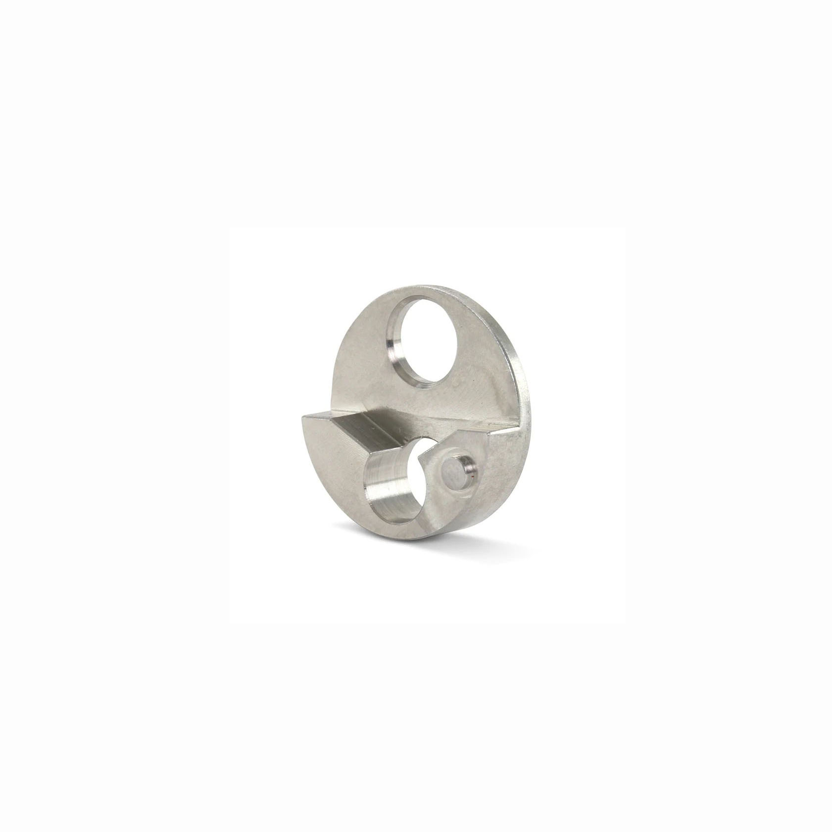
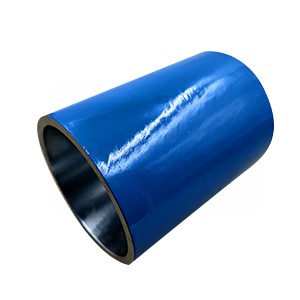
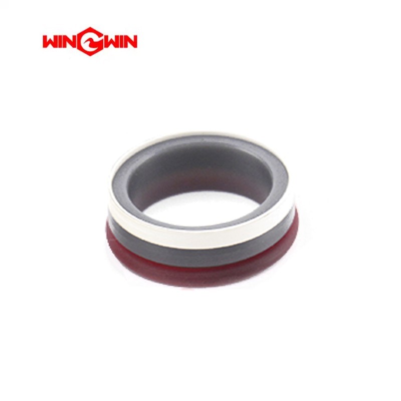
This component is a high pressure (HP) dynamic seal assembly, specifically designed for the intensifier pump in a waterjet cutting system. Its primary function is to create a leak‑tight dynamic seal between the reciprocating ceramic plunger and the high‑pressure cylinder bore, preventing ultra‑high‑pressure water from bypassing the plunger during the compression stroke.
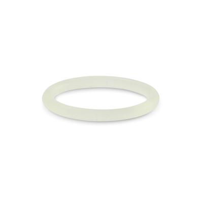
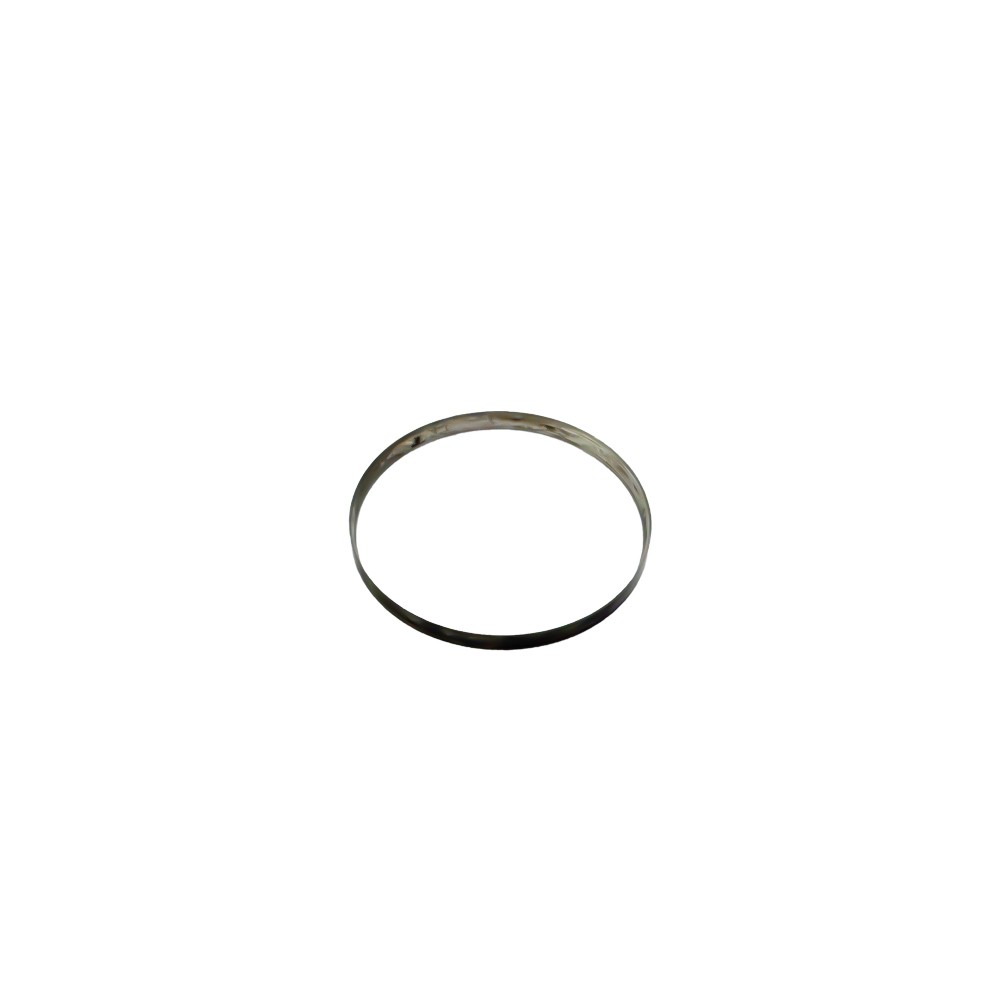
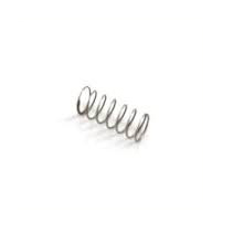
The seal assembly is composed of a dynamic seal with an integrated O‑ring, a rigid backup ring and a packing follower. It is engineered to operate continuously under extreme pressures up to 60,000–90,000 PSI (approximately 4,137–6,200 bar) and is considered a high‑wear consumable component. Its typical service life is 300–1,000 hours, largely depending on water quality, operating pressure and cycle frequency. The assembly is standardised for use in the main intensifier pumps of OEM waterjet equipment.
Applications:
Provides the primary dynamic seal between the reciprocating plunger and the high‑pressure cylinder bore.
Ensures that ultra‑high‑pressure water does not leak past the plunger, maintaining system cutting pressure.
Installed within the high‑pressure cylinder assembly of waterjet intensifier pumps.
Used during scheduled preventive maintenance or when symptoms of seal wear appear.
Features:
High‑Pressure Rating: Engineered for continuous operation at 60,000–90,000 PSI (4,137–6,200 bar).
Premium Material: Manufactured from high‑grade, wear‑resistant composite materials that provide superior sealing performance and durability.
Wear & Corrosion Resistance: Designed to withstand high‑velocity water flow and resist degradation from water and treatment additives.
Critical Consumable Component: Designed to be replaced periodically to protect the more expensive cylinder bore and plunger.
Service Life: Under normal operating conditions with proper water quality, the seal provides 300–1,000 hours of service life.
Maintenance:
Failure Diagnosis (When to Replace):
Visible Water Leakage: Water dripping from the intensifier pump‘s weep hole or drain tube is the primary indicator of high‑pressure seal failure.
Temperature Anomaly: The high‑pressure cylinder or the area around the seal may feel abnormally warm to the touch during operation, indicating internal leakage and friction.
Pressure Drop: A significant drop in cutting pressure or the inability to maintain rated pressure suggests the seal is worn and allowing internal bypass.
Water Contamination in Hydraulic Oil: Milky or discoloured hydraulic oil indicates a catastrophic seal failure that has allowed water to enter the oil system.
Scheduled Preventive Maintenance: Replace the seals as part of a planned maintenance schedule (based on operating hours) rather than waiting for failure to avoid unplanned downtime.
Inspection & Replacement Procedures:
Full Depressurisation (Critical): Before any maintenance, turn the machine off, place the main electrical disconnect in the OFF position, and observe all Lockout/Tagout procedures. Ensure all pressure is relieved or blocked from the hydraulic and high‑pressure circuits.
Clean Area Maintenance: Perform the seal replacement in a designated clean area. Wear disposable gloves to prevent natural oils and contaminants from coming into contact with the new seals.
Disassembly:
Remove the high‑pressure cylinder assembly from the intensifier pump.
Insert a seal removal tool (sleeve) into the cylinder to push the old seal assembly out. Use caution to avoid scratching the cylinder bore.
Remove and inspect the cylinder liner for heat, wear or cracks.
Cylinder Bore Inspection (Critical):
Clean the sealing area on the inside diameter of the cylinder and inspect the bore for rings, scratches, pits, residue or other potential leak paths.
If residue or minor imperfections are present, polish the bore with 600‑grit wet/dry sandpaper using a circular wiping motion only. Do not polish or drag the sandpaper along the length of the cylinder.
Plunger Inspection: Before installing new seals, thoroughly inspect the ceramic plunger surface for scoring, pitting or diameter reduction. A damaged plunger will rapidly destroy a new seal.
Installation:
Lightly coat all new seal components with the manufacturer‘s recommended high‑pressure grease (e.g., FML‑2).
Install the seal assembly using a dedicated seal installation tool (sleeve) to guide the seals past the threads and into the cylinder bore without rolling or pinching.
Ensure correct orientation: the wedge ring chamfer must be installed against the chamfered shoulder of the sealing head, and the O‑ring must face the inlet check valve.
Torque Compliance: When reassembling the high‑pressure end cap, follow the equipment service manual for the specific tightening sequence and torque values. The sequence is typically applied in stages (e.g., 25, 50, 75, 90 ft‑lbs).