
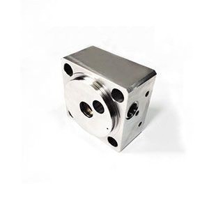
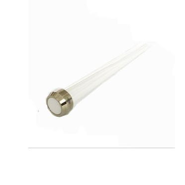
20458299-End-Bell-LH
Product Name: End Bell, Left-Hand (LH) – Part No. 20458299
Description:
The End Bell, Left-Hand (LH) 20458299 is a precision-machined structural component that serves as the hydraulic cylinder end cap on the left side of a waterjet intensifier pump assembly . It is a heavy-duty casing manufactured from high-strength steel or cast iron, designed to withstand extreme pressure cycles up to 60,000 PSI (approximately 4,137 bar) .
As a critical part of the pump’s hydraulic end, the End Bell houses and supports the hydraulic cylinder, oil seals, bearings, and the reciprocating piston assembly . Its primary function is to provide a rigid, leak-proof closure for the hydraulic circuit while ensuring precise axial alignment of the plunger, which is essential for generating the ultra-high pressure water required for cutting .
This component works in conjunction with the Right-Hand (RH) End Bell (Part No. 20458302) to seal the hydraulic cylinder, with both ends secured by heavy-duty tie rods . The "Left-Hand" designation indicates it is specific to one side of the intensifier stack and is typically not interchangeable with the right side due to porting configurations.
Applications:
Closes and seals the hydraulic cylinder assembly on the left side of the waterjet intensifier pump .
Provides a mounting interface for the hydraulic manifold, directional control valve, and pressure sensors .
Houses the hydraulic piston rod seals, bearings, and spacer rings .
Used on 60K (60,000 PSI) and 40K high-pressure waterjet intensifier systems .
Features:
Heavy-Duty Casting: Manufactured from high-strength, fatigue-resistant material to withstand extreme hydraulic pressures and millions of cycles .
Precision Bores: Contains precisely machined internal cavities for housing oil seals and ensuring concentric alignment of the piston rod .
Port Configuration: Features specific hydraulic fluid inlet/outlet ports and sensor mounting points unique to the left-hand side of the pump .
Corrosion Protection: Surface treatment (e.g., plating or coating) provides resistance to hydraulic fluid and moisture .
Component of Intensifier Assembly: Listed as Item #3 in the intensifier parts diagram, alongside Tie Rods, High Pressure Cylinders, and Plungers .
Maintenance:
Failure Diagnosis (When to Inspect/Replace):
External Hydraulic Leakage: Visible oil weeping from the End Bell joints or the sensor ports indicates seal or gasket failure, requiring disassembly .
High Pressure Cylinder Seizure: Difficulty removing the High Pressure Cylinder from the End Bell suggests galling or corrosion on the mating surfaces .
Alignment Issues: If the intensifier is difficult to reassemble, the End Bells may be warped or the threads damaged .
Component Damage: Inspect for cracks, stripped threads (for tie rods), or severe corrosion during pump overhaul .
Inspection and Replacement Guidelines:
Full Depressurization (Critical): Before any maintenance, place the main electrical disconnect in the OFF position, bleed down all high-pressure lines, and follow lockout/tagout procedures.
Remove the End Cap and High Pressure Cylinder.
Remove the tie rod nuts and tie rods retaining the End Bell to the hydraulic cylinder.
Remove the End Bell.
Remove the snap ring, spacer, and oil seals from the End Bell interior.
Reassembly Best Practices (Critical):
Use Assembly Fixture: An intensifier assembly fixture must be used to square the End Bells with each other. If End Bells are assembled out of alignment, oil manifold leakage and breakage may occur .
Torque Compliance: When reinstalling, tighten the tie rod nuts to the specific torque values listed in the equipment service manual (e.g., 160 Nm / 120 ft-lbs) using a crossing (star) pattern to ensure even clamp load .
Lubrication: Apply food-grade or high-pressure grease to new seals (Low Pressure Seal Kit) to aid in installation and prevent dry start-up .
Cross-Reference Information: This component is part of the main intensifier assembly; when replacing seals, it is often paired with a Low Pressure Seal Kit (e.g., 20458797) .
Product recommendation
-
301002-5-Check-Valve-Assembly-15-GPM-60k
-
10079028 HP Coupling , .25 x .25, F/F High Pressure Fitting and Valve Assemblies
-
High Pressure Poppet / Poppet Check Valve (Part No. 510000383)
-
05144506 Ceramic Plunger
-
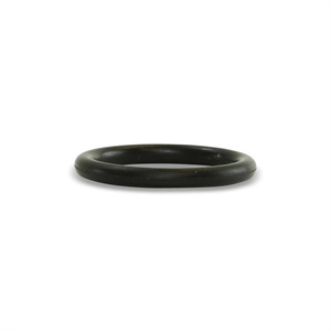
O-ring-014 202570
-
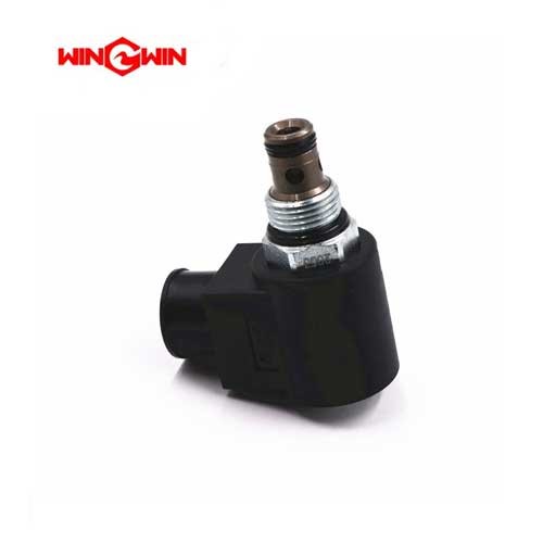
10185585 Solenoid Valve 50HP Water Jet Cutter Parts
-
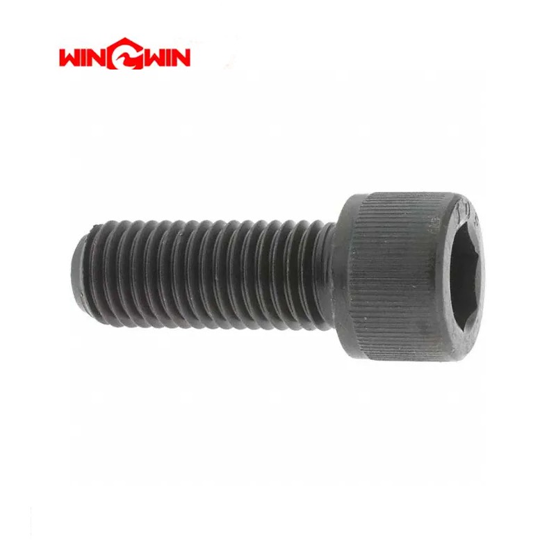
95572897 Hex Head Screw, 1/4-20 x 5/8
