Hydraulic-Manifold-Assembly-72106179
Product Name: Hydraulic Manifold Assembly (Part No. 72106179)
Description:
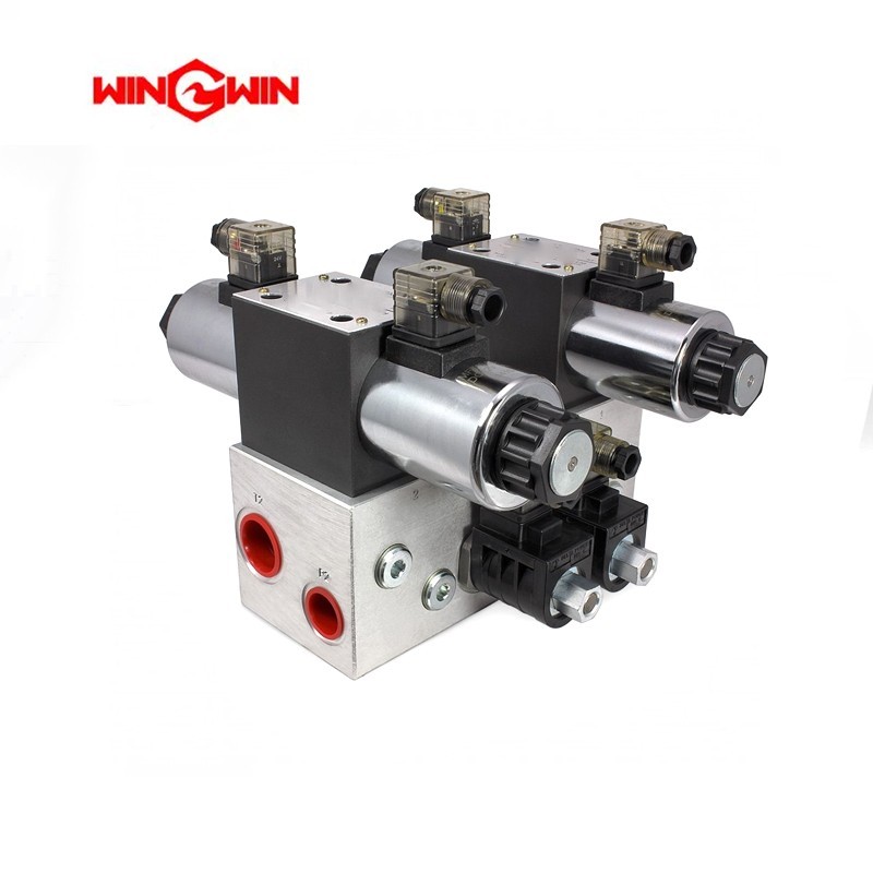
This component is a hydraulic manifold assembly, a central control and distribution block for the hydraulic system in a waterjet intensifier pump . It directs and distributes pressurized hydraulic fluid to various parts of the pump, ensuring the smooth operation of the hydraulic piston, directional control valves, pilot valves, and pressure control components .
The manifold integrates multiple hydraulic flow channels and connection ports into a single, high-strength block. This design helps maintain stable pressure transmission, precise flow control, and efficient pump circulation under ultra-high-pressure operating conditions up to 60,000 PSI (approximately 4,137 bar) .
In a typical intensifier pump, the hydraulic manifold is mounted beneath the intensifier hydraulic cylinder. It houses critical components such as the solenoid-operated directional control valve (4-way valve), high and low pressure control valves, and the main system relief valve, which provides over-pressure protection .
Applications:
Central distribution hub for hydraulic fluid in waterjet intensifier pumps
Houses and integrates directional control valves (DCV), relief valves, and pressure control components
Used during major pump overhauls, seal replacements, and troubleshooting hydraulic issues
Compatible with 60K waterjet intensifier systems
Features:
Integrated Circuitry: Precision-machined internal passages direct fluid for precise piston control and valve actuation
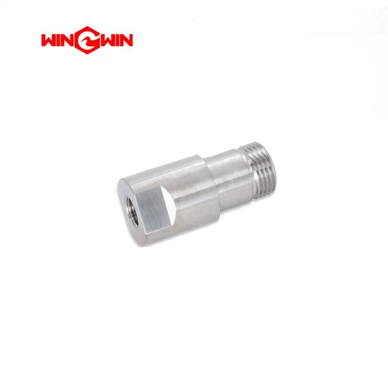
Component Hub: Provides mounting interfaces for solenoid valves, directional control valves, check valves, and pressure gauges
High-Strength Construction: Manufactured from high-grade, corrosion-resistant material (typically steel) to withstand extreme pressure cycling and vibration
Semi-Wear Part Classification: The manifold is subject to hydraulic pressure, vibration, fluid impact, and repeated maintenance cycles, leading to potential thread wear, internal contamination, seal surface damage, or cracking over time
Maintenance:
Failure Diagnosis (When to Inspect/Replace):
External Hydraulic Leakage: Oil weeping from the manifold body or at component interfaces indicates seal failure or a cracked manifold
Intensifier Fails to Shift or Shifts Erratically: If the pump stops at the end of its stroke or cycles irregularly, the manifold may have internal damage or blockage affecting the directional control valve
Pressure Drop: Inability to maintain cutting pressure suggests internal leakage, a worn relief valve, or contamination within manifold passages
Overheating Components: If the manifold body feels hotter than normal, internal leakage may be occurring
Contamination Issues: Dirt or debris in the hydraulic oil can cause internal passages to clog or valve components to stick
Visible Internal Erosion: During overhaul, inspect manifold internal passages for pitting, scoring, or erosion
Inspection and Replacement Guidelines:
Full Depressurization (Critical): Before any maintenance, place the main electrical disconnect in the OFF position, bleed down all high-pressure lines, fully depressurize the hydraulic system, and follow lockout/tagout procedures
Clean Area Maintenance: Perform manifold service in a designated clean area to prevent contamination of internal passages with debris or abrasive particles
Component Inspection Sequence:
Remove the hydraulic manifold from the system
Disassemble and remove all mounted components (solenoid valves, check valves, pressure sensors)
Clean the manifold block thoroughly with a suitable cleaning solvent
Inspect internal passages for blockages, scoring, pitting, or erosion
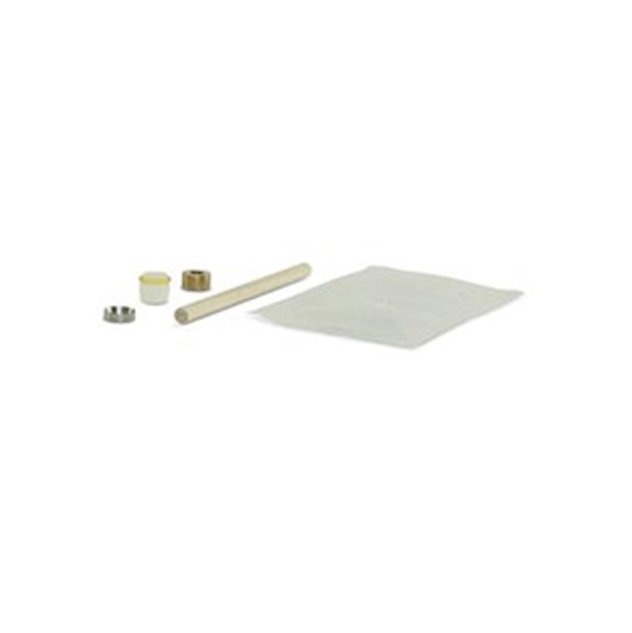
Seal Replacement: Always replace all O-rings, backup rings, and gaskets when servicing the manifold
Torque Compliance: When reinstalling, tighten all mounting bolts and component fittings to the specific torque values listed in the equipment service manual
Thread Lubrication: Apply high-pressure anti-seize lubricant to threads during reassembly to prevent galling
Replacement Criteria: Replace the manifold immediately if cracks are visible, internal passages are severely eroded or clogged beyond cleaning, or threads are damaged. Do not attempt to repair a cracked or severely eroded manifold block
Regular Inspection: It is recommended to inspect this component regularly during major pump maintenance intervals